

How To Repair Xbox 360 Controller
Introduction
Direct forward replacement of the analog joystick on the controller. To much COD Blackness Ops can leave it feeling loose and tin can crusade a drift. Toughest part of this repair was the disassembly of the controller since information technology requires a Torx T8h screwdriver. Brand sure y'all have information technology before starting this repair.
-
-
The left stick is the most common 1 to go bad.
-
Depress the battery release push button on the acme of the controller. Remove the battery holder from the controller.
-
Utilize tweezers or similar instrument, to peel the barcode sticker from the battery compartment.
-
-
-
Remove the seven 9.iii mm T8 Security Torx screws securing the rear instance to the front example.
-
Insert a plastic opening tool between the forepart and rear cases along the left edge of the controller. Rotate the tool toward the front of the controller to pry the 2 cases apart.
-
Grasp the controller by the bombardment compartment and the headphone jack. Lift the battery compartment away from the headphone jack, separating the rear case from the front instance and logic board.
-
-
-
Tilt the lesser example slightly toward the trigger buttons to slide it off the top case
-
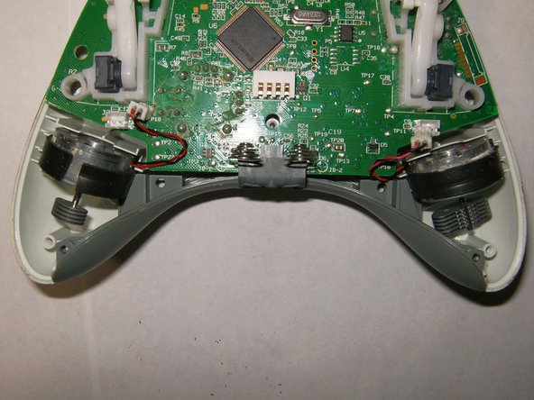
Here is a view of the inside of the controller. Note the vibration motors having different counter weights.
-
Remove the connector from the left motor (controller is positioned upside downwardly, left controller will be shown correct etc.)
-
-
-
Remove the connector from the right motor
-
Both motors are asunder. Find position of the motors inside the case for re-assembly.
-
Remove logic lath
-
-
-
Notice placement of rubber membranes on the front case for reassembly.
-
To remove the covers of the analogs sticks, merely pull them from the mounting pegs.
-
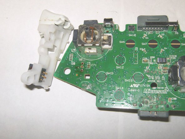
View of the left analog stick to be removed.
-
-
-
To remove the left analog stick, the left trigger push button will have to be removed first. Desolder the iii solder points. Employ desoldering wick and some flux to remove the solder.
-
Left trigger points unsoldered.
-
There are 2 snaps holding the left trigger piece in place, remove those. It may take a bit of force, just but push the snap over and down.
-
-
-
When removing the left trigger, make sure that the points are unsolderd properly, gently pull the trigger down.
-
Left trigger removed.
-
With the left trigger removed, only turn the logic board over and find the 14 solder connections
-
-
-
Use a desoldering wick and some flux to remove the solder.
-
Ensure that no other components get either desoldered or otherwise rut damaged.
-
Here, all points take been desoldered.
-
-
-
Pull off the 3D analog stick gently to ensure that all solder connections are unsoldered.
-
Remove the analog stick
-
Put the new 3D analog stick in place. Brand sure that it is seated affluent against the board.
-
-
-
Apply some flux to the solder points and the leg of the analog stick.
-
Solder the connections in place.
-
All points soldered back in place. The liquid black debris is flux. This tin can exist removed past cleaning the board with some isopropyl alcohol after the soldering.
-
-
-
Here is the board with the new sticks and the left trigger button resoldered.
-


Decision
To reassemble your device, follow these instructions in reverse gild.
Embed this guide
Choose a size and re-create the lawmaking below to embed this guide as a small widget on your site / forum.
Preview

Source: https://www.ifixit.com/Guide/Xbox+360+Wireless+Controller+Left+Analog+Stick+Replacement/17887
Posted by: nortondregat.blogspot.com
0 Response to "How To Repair Xbox 360 Controller"
Post a Comment